The Complete Guide on Aerospace Electronics PCB Assembly & Design

By | Date posted: | Last updated: February 15, 2023
aerospace-electronics

There is extraordinarily little room for mistakes in the Aerospace mechanism because if any fault happens in space, it is too far for scientists to reach for its retrieval. And as most aerospace machines are electronic devices, some extra attention you have to put in to ensure the efficiency of the PCB Assembly of each electrical aerospace tool.

From standard to the reliability, security in every aspect has to be ten out of ten in space-based systems. To provide that as a manufacturer, you need advanced software, evolved hardware, skilled workers, and many more things, which we discussed in this article to give you a complete guide. So, check it out to know what you need to develop PCB Assembly & Design for an aerospace electronics exceptional performance.

Basic Features of Aerospace PCB Assembly & Design:

The feature of developing an aerospace electronics PCB assembly & Design is not all similar to any simple electronic PCB, and it needs some strict requirements. Any problem in PCB causes landing problems for aerospace, signal trouble to the Control team, or even premature failure before landing. So, to make a suitable, accurate PCB, the features it requires are-

Durability:

Aerospace is most of the time work in an extended period like from months to year without your direct reach like in the air or a faraway from you. So, if the PCB assembly is not efficient enough to last that much time it will be an unbelievably tough situation to handle. Even a long budget project can break down like a sandcastle due to the short-lived components.

So best to prevent such a tragic situation at the time of manufacturing by applying only the best quality, longevity components in the application. It may seem at a first cost a bit high, but ultimately it saves your fortunes which may require future replacement of the material.

Specific material selection:

The material of the PCB assembly manufacturing has to be extremely specific at the time of aerospace electronic devices. Every specific order of aerospace needs exactly suitable material to fit the need of unique contracts.

Always use high-quality materials in aerospace electronics because it is worked in an extremely sensitive aerodrome. Check everything before delivery, like is it working or not. Make sure the materials are flexible to changes. There are very frequent thermal and electrical changes that happen in space.

Bearing ability of the adverse environment:

PCBs (Printed Circuit Boards) of aerospace have to withstand some adverse environmental conditions like extreme heat, outrageous radiation, or severe pressure.

As it is important to protect the outer part, at the same time, it is also very crucial to safeguard the internal device from the radical thermal surge. Because in the engine, the temperature is even more than thousands of degrees which can barely be overcome by ordinary materials. And Another cause of the hazardous environment is the rapid change of different layers of the atmosphere when launching into space as the engine is mostly made of electronic devices. Hence, the PCB’s substance also has to bear such heat.

Testing after manufacturing:

After the PCB assembly manufacturing, you have to check and double-check by thoroughly testing by following the right protocol of inspection. To assure the quality and proficiency of the product delivery, testing is especially important. Because if it fails to work in the testing period, it can be replaced, but if it ceases to function in space, there will not be any second chance to recover.

In testing, you have to primarily consider thermal testing. Vibration testing is another important testing also. Except that internal testing like security testing, quality testing also has to examine.

Risk factors:

Nothing is flawless; besides all testing and examining, there are always some risks present in every field. But in aerospace divorce, you can’t take a risk by any chance. So always tie up with this manufacturer who has good reputation certified skills and has a good public review. Always inquiries about the company before making any contract.

Some points you have to keep in mind at the time of developing aerospace devices:

Here, we are sharing some special points you have to keep in mind to develop the best aerospace device –

  • Choose only the PCB Assembly, which is the suit best according to your demand, standard.
  • Go for the manufacturer you provide updated application, software, hardware, etc.
  • Always prefer quality first. The substandard quality is the root of any failure in the future if it happens.
  • Try to choose easily available PCB components and testify to every component before final purchasing.

Conclusion:
We hope the upper given guideline will help you in choosing the best aerospace PCB Assembly & Design and able to meet all your expectations on your dream project.

At Technotronix, we have over 4 decades of experience in providing PCB industrial solutions. We are therefore well-poised to understand the various issues than plague the industry and how robust testing can help overcome these issues. Our PCB manufacturing facilities hold extensive number of certifications and licenses to meet complete turnkey PCB aerospace solutions. For your any kind of requirements, Get a quick PCB assembly quote.

Best Long-Term Practices for Electronic Assembly Manufacturing with the Wave Soldering!

By | Date posted: | Last updated: February 14, 2022
electronic-assembly-manufacturing

In this rapidly growing electronic industry, innovative ideas are very important to be in the market. Wave Soldering is an important feature for the electronic assembly manufacturing to run the PCB in the long term.

Nowadays, Wave Soldering reduces to a noticeable level, but its importance is still unreplaceable in long scale PCB Assembly.

As wave soldering is an important component of PCB, in this article, we broadly discussed it so that you can grasp a good idea about its importance.

What is the wave soldering process?

Wave Soldering is the process of providing the PCB electrical second soldering through a joint to make the PCB assembly more reliable, efficient, and long-term.

The wave soldering is done by both through hole mount or surface mount processes. But the surface mount process is most commonly used in the advanced infra-red wave soldering methods.

Factor Consideration of Solder Bridging in Wave Soldering procedure:

Myriad factors have to be analyzed at the process of solder bridging in wave soldering. From the component to the design process, everything has to impose only after a thorough investigation. The factor which has to evaluate are –

Length of lead:

The lead length used in the soldering has to be medium in size, if it becomes short, it will be unable to reach the capacitor, or if it is long, it causes webbing between the pins. A perfect lead length is that which can easily transfer the heat. The best way to measure the almost exact size is by the ratio of design and PCB’s thickness.

PCB Designing Consideration:

Pin count is a factor to consider at the time of design of wave soldering in electronic assembly. For the significance bridging two or more than two-row parallel pins are the perfect number.

For fine pitch, must confirm that a large number of perpendicularly oriented pins are present that influence the connectors of the bridging to do the work efficiently.

PCB Component Consideration:

Ensure that the axial and radial component of soldering is appropriately set up. This alignment of the components helps avoid most lifting crises.

An inappropriate positioning can cause increased length and can lift the element out of place.

Tooling consideration:

An appropriate PCB orientation is very important in tooling the wave soldering. In case of good waving, the board’s angle has to be between 15-30 degrees. That helps the pin to migrate when required. And it is very useful for large pins also where the connector is almost parallel to wave soldering.

The space between wave openings and the flow channel of the pallet of soldering is very important.

The height of the side of the button of the components of the surface mount process is also an important tooling consideration. It impacts the number of pallet requirements, the capacity of the flow of soldering. The length versus width ratio is a key component of any defect in it hampered the flow of soldering and another wave deformity.

Process Consideration:

In the process, the wave length, the flow ratios between lands and lamina waves are examined. With the rise in the ratio, the component of the PCB lifted. The height of the wave is less than half of the PCB thickness to reduce the chance of turbulence flow. Not only the height ratio, other factors like the angle of the pallet, but the oscillation of the conveyor also has to be considered.

Design consideration:

For the best design of the wave soldering the copper, the layer is directly connected through a hole to the wave plate. It works for the proper flow of heat, which is good for adequate thermal relief.

The second thing to consider in design is the ratio of lead diameters with the through-hole diameter of the PCB plate. The ratio measuring 0.6 is the best for wave soldering.

Solder Void:

Soldier void is very important because any problems in it cause moisture problems in the PCB. The voids are small holes that entrap gas during soldering, which outgasses the joints because most of the PCB is moisture sensitive, and this out grass process makes the cabinet dry.

Solder Ball:

A solder ball is aimed to adhere to the wave soldering process at the point it requires. Solder ball controls the flux application. It resists the flux when its flow is high, promoting the wave when the flux is low. Thus, it controls the temperature of the Assembly also.

Conclusion:
The Wave Soldering is recommended to the manufacturer who wants to handle a long-term Electronic Assembly. Most manufacturers don’t consider it, so it will be a good point to make a difference. With the market’s evolution, you also have to be evolved to challenge the industry and fulfil users’ demands.

Technotronix is a leading PCB Assembly company which has been operating for the last four decades. We are upgrading ourselves every day and offering the finest circuit board assembly, circuit board designs and fabrication services to our clients. We overcome every challenge that our customers can face, which helps to get perfect momentum in PCB making. The PCB designing results from Technotronix to evolve with time and easily place their place in the global PCB market.

Get a Free quote for PCB Assembly!

What Standards and Regulations utilize for Medical PCB Assembly?

By | Date posted: | Last updated: June 7, 2024
Medical PCB Assembly

The use of Printed Circuit Boards has been ubiquitous across industries. Like with other industries, PCBs are also finding extensive application in the medical industry as more and more medical research and treatment methods become technology driven. With lives of patients at stake, it goes without saying that these devices are mission critical and that stringent guidelines need to be followed when it comes to Medical PCB Prototype. Clearly there cannot be an instance where there is a malfunctioning instrument when a critical, lifesaving medical procedure is being carried out. Little surprise then that these instruments need to be manufactured to some very exacting standards.

There need to be strong protocols related to PCB design, fabrication, PCB assembly, testing and inspection. Even though medical devices are varied, and their use is widespread across functions and there need to be specific standards and regulations related to their use, here is a quick overview of the broad Medical PCB Assembly Standards and Regulations:

IPC Standards

Presently called Association Connecting Electronics, its acronym comes from its former name i.e. Institute for Printed Circuits. It is an industry body that has issued a series of standards for circuit boards. These include:

medical-pcb
IPC-A-600: This is to do with acceptability of the circuit boards.
medical-grade-circuit-board
IPC-A-6012: This deals with the performance specifications for PCBs.
medical-printed-circuit-boards
IPC-A-610: This standard is to do with acceptability of electronic assemblies. Under this, there are different standards for:

  • Harnesses
  • Soldering
  • Enclosures
  • Cables
pcb-assembly
ISO 9000: A commonly known standard, it stands for International Organization for Standardization. There are several standards under this series that are to do with quality of circuit board design, its manufacturing as well as testing. Usually, a CM is certified in one of the ISO 9000 standards, with ISO 9001 being the most common.
medical-pcb-manufacturer
FDA: 21 CFR 820, introduced by the U.S. Food and Drug Administration is a quality system regulation, whereby with the relevant certification the medical device OEMs need to carry out their manufacturing and control processes. This then ensures that their product meets the necessary requirements.
  • The certification requires that all manufacturing phases are clearly documented so that products are built as per regulation
  • It also ensures that processes are in place for risk management and design control.
  • Manufacturers are also required to develop an audit system to track their own performance as far as the process goes.

With these standards in place, it is an assurance to regulators as well as to clients that the manufacturer is fully committed to quality and that it has the necessary systems as well as processes in place.

This of course, means that in order that your medical requirement meets the necessary regulatory standards, you need to partner with a contract manufacturer who works with these standards. If you have been looking for a contract manufacturer that offers Medical PCB Prototype that adheres to the highest standards, your search ends at Technotronix. Not only are we certified to the highest industry standards, but we also have a highly trained team that has the requisite experience and expertise when it comes to Medical Printed Circuit Board Assembly. The fact that we are also equipped with industry best practices ensures you do not need to reinvent the wheel. When you partner with us, you can rest assured that you will get medical equipment that stands tall against the exacting requirements.

TechnoTronix excels in providing solutions to medical mechanism. We offer medical electronic solutions to injection Molding and packaging and complete product manufacturing per layout. With over 4 decades of industry experience and rich knowledge to boot, little surprise then that Technotronix has emerged as a preferred partner of choice across industries including the Medical Printed Circuit Board Assembly.

Request a quick quote for Medical PCB Assembly

Top Considerations while selecting Cable and Wire Harness Assembly to enhance the performance of your final product!

By | Date posted: | Last updated: September 9, 2024
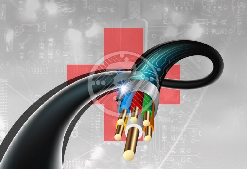
cable-and-wire-harness-assembly

Do you know what is the key component of any electronic or electrical systems? It is a cable and wire harness but unfortunately, many treat it as an afterthought. While you design your systems, cable and wire harness assembly should be the first thing to be considered in the design phase. Various components are required in cable harness assembly and each component affects the performance of the cable and wire harness assembly.

In the cable and wire harness assembly, either over-design or under-design will have negative impacts on the performance of the finished assembly.

Environment

The first thing you need to think of is the environment in which the assembly is going to be used. If it is going to be used in a dynamic installation or a harsh environment, you should be aware that it will be exposed to flexing, and your components of the cable and wire harness assembly should be able to withstand the flex. If it is going to be used in a cleanroom environment, make sure the assembly can withstand the sunlight and moisture.

Materials

Use the best materials for meeting the expectations of the assembly installation, for signal transmission over the assembly, and safety certifications that comply with the environment.

Conductors – Based on the application, the number and type of conductors to be included will be determined. There are different options for the conductive material and the most widely used one is copper. Copper retards corrosion and you can also go for copper-clad steel or copper alloys if you want to add strength. You can also use copper along with tin for various coatings. Silver or nickel coatings are used for letting the cable assembly be used in environments of high temperatures. They can be used as a single solid strand or many smaller conductors as they can help in overcoming the rigidity of the wires and make them more flexible.

Primary Insulations – The material, type, and thickness of the insulator of the primary conductors depend on the application where the custom cable assembly is used. Depending on the temperature the assembly will be exposed to, the voltage levels, the type, chemicals the assembly will be subjected to, and how harsh the environments will be, you should choose the appropriate materials. If your assembly needs to work at extreme temperatures, you need more rugged compounds for proper functioning. You may also have to foam them for higher-speed signals.

Cable Type

Different applications require different cable types. For instance, a coaxial cable is used for RF applications, shielded cable for noise-sensitive applications, ribbon cable for insulation displacement contact, and simple equipment wires for simple applications. The conductor wires must be sized properly to ensure that the current and voltage drops are acceptable in all operating conditions.

Cabling of conductors

When pairs of the same cable are in close proximity, the most common problem is the noise. So you can go for twisting of the pairs of cables for countering the effect. The conductors should be cabled or twisted for reducing the noise in the transmission of the signals. It is also aesthetically pleasing.

Shielding

With several shield options, you can go for metallize foil that has fairly good flexibility and is good at higher frequencies. You can go for a braided shield where there are many small diameter wires braided onto the cable core using special equipment. Although this is costlier than a foil shield, it offers better shielding at lower frequencies and offers better flex life. We also have a spiral shield that offers excellent flexibility with long flex life. You can go for a combination of foil and braid shields which offer excellent protection at all frequencies.

Outer Sheath

After finishing the cable core construction, an outer sheath is applied that acts as a protective covering. This outer sheath has to be tough for protecting the cable from harsh environments and be flexible for allowing the movement of the assembly throughout the life cycle of the equipment. It has to be chemically resistant and also be semi-conductive. PVC is the most widely used compound and other materials include urethane-based products, elastomer-based products, fluorocarbons, and other alloys that offer low-smoke, low acid generation, and low toxicity.

Connectors Reliefs

Among several options available for the cable assembly, you need to check the type and speed of the signal being transmitted. If a high-speed signal is to be transmitted, go for a solder type connection; if a power is to be sent through the assembly, a crimp type should be chosen.

Routing

Make strategic use of the cable space for avoiding sensitive parts of the system from being damaged. This also improves the effective use of cable assembly. Cable assemblies have to be routed close to the chassis in the systems where there are vibrations or movements. In high-vibration applications, you should consider including anti-wear measures like cable clips.

Safety Standards

Safety is one of the major concerns while designing a cable assembly and wire harness. The key element here is the location where the assembly will be used as the safety certifications and standards vary from a region to region. You need to make sure that the environmental standards are met by your assembly. The regulatory and safety standards that are meant for the enforcement and testing of electrical devices differ. In the USA, we have UL and CSA standards as the regulatory and safety standards. Also, RoHS directives are another environmental standard that limit the use of hazardous substances in electrical products.

Besides these, your cable assembly and wire harness assembly must also meet the industry standards based on the specific performance criteria.

Summary

You have to consider a lot many things while designing your cable assembly and wire harness for your application. Be clear about your specifications and design needs before you begin your assembly and manufacturing process. If you disregard any of the factors, the performance of your final product could be affected. We recommend you bring up all the specifications to your CM who has taken up your cable and wire harness assembly needs.

At Technotronix we have 40 years of experience in manufacturing and assembling industry leading products. Equipped with state-of-the-art equipment and skilled personnel we offer products to meet your bespoke requirements. Technotronix can be a trusted Cable Assembly Manufacturer partner for you, which will give you ample smart solutions related to Printed Circuit Boards.